Levitating Ball using a Fuzzy Control System
By Mark Bowers and Muawea Rawashdeh
May 3, 2010

Levitating Ping-Pong Ball Setup
For our final project in Dr. Richard E. Haskell's ECE470 class (Microprocessor-based System Design) at Oakland University, Muawea Rawashdeh and I built a system to levitate a ping-pong ball at a desired height with the use of a fuzzy control system running on an HCS12 microcontroller.
A ping-pong ball is trapped within a Plexiglas tube, with a duct fan mounted at the base to provide life for the ball. An ultrasonic sensor mounted within the tube provides a feedback loop for the system, while an infrared sensor mounted at the side, parallel to the tube, provides for user input.
The basic goal is to make the ball hover smoothly at a desired level within the tube, by correctly controlling the speed of the fan mounted at the bottom of the tube, and by correctly interpreting the feedback information provided by the ultrasonic sensor mounted within the tube. The setup is that of a classic feedback loop. The system input (fan speed) is changed, and as a result the output (ball speed and position) is changed. The output is continuously observed to determine how to further adjust the input. Our project uses "fuzzy logic" to determine the proper output.
To those unfamiliar with the term "fuzzy logic", it might incorrectly imply a system that is shoddy and unfocused. Rather, fuzzy logic simply refers to a system of continuous, multi-valued logic. Instead of dealing with crisp, discrete values of “true” and “false” that are found in digital logic, values can vary continuously between “true” and “false”. These continuous values are then interpreted with the use of membership functions, which designate ranges of these continuous values to have a particular quality. For many control systems, the "fuzzy" approach is advantageous, as it acknowledges the imprecision and uncertainty of the physical world, and allows the system to behave more appropriately in it.
In our system, membership functions were created to describe (1) the ball’s current position relative to the center: negative far, negative close, zero position, positive close, and positive far:

Membership Function for Ball Position
And (2) the ball’s current speed: negative fast, negative slow, zero speed, positive slow, and positive fast:

Membership Function for Ball Speed
An output function was created with levels of motor speed based on the effect it has on the ball: negative high, negative low, zero, positive low, and positive high. (“Negative high” causes the ball to drop quickly, “negative low” less quickly, etc.) These outputs are singletons, defuzzified by the system with the weighted-average method.
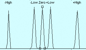
Output Function
A fuzzy Karnaugh map was then made, consisting of the desired output based on the degree of membership in the ball speed and ball position functions. This map is filled with values that make logical sense. For instance, if the ball is high in the tube (positive far), and falling (negative fast), then the motor is set to a value close to “zero motor” to allow the ball to drift downward. Alternatively, if the ball is very low in the tube (negative far) and is falling (negative fast), then the motor is set to a value close to “positive fast” to move it back into the zero position. This system attempts to settle to a point where the ball position is in the center (zero position) and where it is not moving (zero speed), and the speed of the motor is such that it only blows enough to maintain the position (zero motor).

Fuzzy Karnaugh Map
A narrow-beam ultrasonic sensor, the LV-MaxSonar-EZ4 was used to detect the position of the ball within the tube. This model was the narrowest beam sensor available. Models with wider beams did not function properly in the tube, presumably due to internal reflection of the sonar waves. This sensor contains an embedded PIC microcontroller and can output to serial, pwm, or analog. (We used analog.) It provides distance in a range from 0 to 6.5 meters, with a one-inch resolution. An infrared sensor, the Sharp 2Y0A02F, (shown below, at right) was used to detect the height of the user's hand. This sensor gives an analog ouput, and is capable of detecting ranges from 20-150cm, with a resolution of 0.33cm.

Ultrasonic Sensor (For System Feedback)
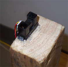
Infrared Sensor (For User Input)
A duct fan was used to blow air inside the tube and move the ball. An external 3V power source was controlled using PWM, driven with an IRF530 transistor operated by the HCS12 microcontroller.

MiniDragon HCS12 board

Duct Fan
The software for this project was coded in C in CodeWarrior, and runs on a Freescale HCS12 project board, the Wytec miniDragon2-Plus. Upon first starting, the HCS12 computes slopes for the membership functions, and stores this for use by the fuzzy assembly functions later. This is done because the HCS12’s fuzzy functions use two points and two slopes (instead of simply four points) to describe a membership trapezoid. Also on start-up, the motor is blasted for 1.5 seconds to ensure the ball is not stuck at the bottom of the tube. After this, the only task left in main() is to update the LCD with some debug values such as current ball velocity and speed, the desired position read from the IR sensor, and the speed output to the motor.

Sliding Membership Function
The entire critical functionality of the system resides within the real-time interrupt on the HCS12, set with a period of 10.24 milliseconds. Upon first entering the interrupt, a height is recorded by reading the ultrasonic sensor. The height is read as an analog value with the A-to-D converter, with a function that scales this value to the length of the tube, from 0 to 255. After looping 20 times (roughly 200ms), another height is recorded, and from this, the speed of the ball is determined. Next, the value from the IR sensor is recorded. The analog value from the IR sensor has a non-linear output, so a function linearlizes this value, and appropriately scales and saturates it, given the length of the tube, again from 0 to 255. The value collected for our desired height from the IR sensor is then used to shift the detected ball location in such a way that it effectively shifts the position membership function, so that the ball settles at the desired height.
Next, the fuzzy calculation is performed. The HCS12 is special in the fact that is has assembly instructions specifically for the purpose of doing fuzzy logic calculations. According to the Freescale datasheets, this allows the HCS12 to perform fuzzy calculations with 1/5th of the code, and at 50 times the speed of a comparable microcontroller doing the same calculation! The “MEM” instruction determines the grade of membership a value has in a given function, the “REV” instruction fires the fuzzy logic rules, and the “WAV” function performs weighted-average defuzzification on the output membership function. These fuzzy assembly instructions are called from C functions, and used to fill the position and velocity membership functions, fire the rules, and defuzzify the output.
A video of the project in action is shown below:
In the end, this was a worthwhile and interesting project to work on. We learned the basics of constructing and tuning a fuzzy control system. Difficulties with sensors and aerodynamics issues proved to be a learning experience. In the future, this project can serve as a good classroom demonstration platform to compare various feedback loop algorithms: fuzzy, PID, bang-bang control, etc.